Get Affine from Image#
Latest demo params files / scripts: chiahao3/ptyrad
Documentation: https://ptyrad.readthedocs.io/en/latest/
PtyRAD paper: https://doi.org/10.1093/mam/ozaf070
PtyRAD arXiv: https://arxiv.org/abs/2505.07814
Zenodo record: https://doi.org/10.5281/zenodo.15273176
Box folder: https://cornell.box.com/s/n5balzf88jixescp9l15ojx7di4xn1uo
Youtube channel: https://www.youtube.com/@ptyrad_official
Note: This notebook is designed to demonstrate how to estimate affine transformations from image given prior information of the underlying structure
Authors:
Dr. Guanxing Li (initiated the idea), guanxing.li@cornell.edu
Dr. Chia-Hao Lee (refine the notebook), chia-hao.lee@cornell.edu
00. Imports#
import os
work_dir = "H:/workspace/ptyrad"
os.chdir(work_dir)
print("Current working dir: ", os.getcwd())
Current working dir: H:\workspace\ptyrad
import numpy as np
import matplotlib.pyplot as plt
import PyQt5 # This is needed for interactive point selection with matplotlib (i.e., pip install PyQt5)
from tifffile import imread
from skimage.transform import AffineTransform, warp
01. Define functions#
## Define PtyRAD functions here so you can run this without the PtyRAD python environment
def compose_affine_matrix(scale, asymmetry, rotation, shear):
# Adapted from PtychoShelves +math/compose_affine_matrix.m
# The input rotation and shear is in unit of degree
rotation_rad = np.radians(rotation)
shear_rad = np.radians(shear)
A1 = np.array([[scale, 0], [0, scale]])
A2 = np.array([[1 + asymmetry/2, 0], [0, 1 - asymmetry/2]])
A3 = np.array([[np.cos(rotation_rad), np.sin(rotation_rad)], [-np.sin(rotation_rad), np.cos(rotation_rad)]])
A4 = np.array([[1, 0], [np.tan(shear_rad), 1]])
affine_mat = A1 @ A2 @ A3 @ A4
return affine_mat
def decompose_affine_matrix(input_affine_mat):
from scipy.optimize import least_squares
def err_fun(x):
scale, asymmetry, rotation, shear = x
fit_affine_mat = compose_affine_matrix(scale, asymmetry, rotation, shear)
return (input_affine_mat - fit_affine_mat).ravel()
# Initial guess
initial_guess = np.array([1, 0, 0, 0])
result = least_squares(err_fun, initial_guess)
scale, asymmetry, rotation, shear = result.x
return scale, asymmetry, rotation, shear
def plot_affine_transformation(scale, asymmetry, rotation, shear):
# Example
# plot_affine_transformation(2,0,45,0)
A = np.eye(2)
Af = compose_affine_matrix(scale, asymmetry, rotation, shear)
plt.figure()
plt.title(f"Visualize affine transformation \n (scale, asym, rot, shear) = {scale, asymmetry, rotation, shear}", fontsize=14)
# Add origin and scatter points
plt.scatter(0, 0, color='gray', marker='o', s=3)
plt.scatter(A[:,1], A[:,0], label='Original')
plt.scatter(Af[:,1], Af[:,0], label='Transformed')
# Adding arrows
plt.quiver(A[0,1], A[0,0], angles='xy', scale_units='xy', scale=1, color='C0', alpha=0.5)
plt.quiver(A[1,1], A[1,0], angles='xy', scale_units='xy', scale=1, color='C0', alpha=0.5)
plt.quiver(Af[0,1], Af[0,0], angles='xy', scale_units='xy', scale=1, color='C1', alpha=0.5)
plt.quiver(Af[1,1], Af[1,0], angles='xy', scale_units='xy', scale=1, color='C1', alpha=0.5)
# Adding grid lines
plt.grid(True, linestyle='--', color='gray', linewidth=0.5)
plt.ylim(-2,2)
plt.xlim(-2,2)
plt.gca().set_aspect('equal', adjustable='box')
plt.gca().invert_yaxis() # Flipped y-axis if there's only scatter plot
plt.xlabel('X')
plt.ylabel('Y')
plt.legend()
plt.show()
def pick_points_with_keyboard(img, n=3, step=1.0):
"""
Interactively pick n points on an image using mouse and keyboard.
Args:
img: Image array to display
n: Number of points to pick (default: 3)
step: Movement step size for arrow keys in pixels (default: 1.0)
Returns:
numpy array of shape (n, 2) containing [x, y] coordinates
"""
pts = [] # Store confirmed points
current = {"x": None, "y": None} # Current point position (before confirmation)
done = {"flag": False} # Flag to track completion
# Create figure and display image
fig, ax = plt.subplots(figsize=(12, 12))
fig_width_inches = fig.get_figwidth()
base_fontsize = fig_width_inches * 2 # Adjust multiplier as needed
ax.imshow(img, cmap="gray")
ax.set_title(
f"Pick {n} points\n"
"Mouse click: place point | Arrow keys: move | Enter: confirm\n"
"Tip: click inside the figure FIRST so it receives keyboard focus."
, fontsize=base_fontsize)
# Red marker for current (unconfirmed) point
marker, = ax.plot([], [], 'ro', markersize=6)
def redraw():
"""Update the display of the current point marker."""
if current["x"] is None:
marker.set_data([], []) # Hide marker if no current point
else:
marker.set_data([current["x"]], [current["y"]])
fig.canvas.draw_idle()
def on_click(event):
"""Handle mouse click events to place a new point."""
if event.inaxes != ax:
return
# Set current point to clicked location
current["x"], current["y"] = float(event.xdata), float(event.ydata)
redraw()
def on_key(event):
"""Handle keyboard events for point movement and confirmation."""
if event.key is None:
return
# Enter key: confirm current point
if event.key == "enter":
if current["x"] is None:
return # Allow Enter even when no point exists (no error)
# Save the confirmed point
pts.append([current["x"], current["y"]])
print(f"Point {len(pts)-1} (x,y) confirmed: ({current['x']:.2f}, {current['y']:.2f})")
# Draw confirmed point as green circle
ax.plot(current["x"], current["y"], 'go', markersize=6)
# Clear current point after confirmation
current["x"], current["y"] = None, None
redraw()
# Close figure when all points are collected
if len(pts) >= n:
done["flag"] = True
plt.close(fig)
return
# Don't allow movement if no current point exists
if current["x"] is None:
return
# Determine step size: Shift key multiplies step by 10
s = step
if "shift" in (event.key or ""):
s = step * 10
# Arrow keys: move current point
if event.key in ("left", "shift+left"):
current["x"] -= s
elif event.key in ("right", "shift+right"):
current["x"] += s
elif event.key in ("up", "shift+up"):
current["y"] -= s # Note: imshow y-axis points downward
elif event.key in ("down", "shift+down"):
current["y"] += s
redraw()
# Connect event handlers
cid_click = fig.canvas.mpl_connect("button_press_event", on_click)
cid_key = fig.canvas.mpl_connect("key_press_event", on_key)
# Add axis labels
ax.set_xlabel('X-axis', fontsize=base_fontsize)
ax.set_ylabel('Y-axis', fontsize=base_fontsize)
# Show plot and block until window is closed
plt.show(block=True)
# Disconnect event handlers
fig.canvas.mpl_disconnect(cid_click)
fig.canvas.mpl_disconnect(cid_key)
# Convert points list to numpy array
pts = np.array(pts, dtype=np.float64)
# Validate that enough points were collected
if pts.shape[0] < n:
raise ValueError(f"Only got {pts.shape[0]} points. "
f"Click inside the figure, then use Enter to confirm each point.")
return pts
def get_affine_transformation_from_points(P0, P1, P2, target_angle=90.0, target_ratio=1.0, v1p_length=None, pixel_size=None):
'''
Calculate affine transformation from given points following user-defined constraints (angle, ratio, and length)
# ========================================
# User-specified geometric constraints
# ========================================
target_angle = 90.0 # Angle from v1 to v2 in degrees (clockwise rotation in image coords), default: 90
target_ratio = 1.0 # |v2p|/|v1p| ratio, default: 1.0
v1p_length = None # Target length for v1p in real units (e.g., nm), default: None
pixel_size = None # Real-world size per pixel, default: None
'''
# ========================================
# Input points and vectors
# ========================================
# P0, P1, P2 are already defined as (x, y) coordinates
# Compute vectors from P0
v1 = P1 - P0 # Roughly along with fast scan direction (horizontal)
v2 = P2 - P0
# ========================================
# Sanity checks on input vectors
# ========================================
L1 = np.linalg.norm(v1)
L2 = np.linalg.norm(v2)
if L1 < 1e-9:
raise ValueError("v1 is too small; P0 and P1 are nearly identical.")
if L2 < 1e-9:
raise ValueError("v2 is too small; P0 and P2 are nearly identical.")
# Check if v1 and v2 are too collinear
# Normalize the cross product by the product of magnitudes
cross_product = v1[0] * v2[1] - v1[1] * v2[0]
normalized_cross = abs(cross_product) / (L1 * L2)
# normalized_cross = |sin(theta)| where theta is the angle between vectors
# Values close to 0 mean vectors are nearly parallel
if normalized_cross < 1e-3: # ~0.06 degrees
raise ValueError("v1 and v2 are nearly collinear; pick more independent vectors.")
print("Original vectors:")
print(f" v1 = {v1}, |v1| = {L1:.3f}")
print(f" v2 = {v2}, |v2| = {L2:.3f}")
print(f" Original ratio |v2|/|v1| = {L2/L1:.3f}")
# Calculate original angle (from v1 to v2)
# In image coordinates: arctan2 gives us the angle directly
angle_v1 = np.arctan2(v1[1], v1[0])
angle_v2 = np.arctan2(v2[1], v2[0])
# The rotation angle from v1 to v2 (can be positive or negative)
original_angle = np.degrees(angle_v2 - angle_v1)
# Normalize to [0, 360)
if original_angle < 0:
original_angle += 360
print(f" Original angle (v1→v2 rotation) = {original_angle:.2f}°")
# ========================================
# Construct target vectors v1p and v2p
# ========================================
# v1p: keep v1 unchanged (assume it's close to fast scan and fast scan is roughly correct)
v1p = v1.copy()
# v2p: construct based on angle and ratio constraints
# Target length for v2p
L1p = np.linalg.norm(v1p)
L2p = target_ratio * L1p
# Direction of v2p: rotate v1p by target_angle
angle_rad = np.radians(target_angle)
# Standard rotation matrix (counterclockwise in Cartesian, and clockwise in typical image coordinate due to inverted y-axis)
cos_a = np.cos(angle_rad)
sin_a = np.sin(angle_rad)
rotation_matrix = np.array([[cos_a, -sin_a],
[sin_a, cos_a]])
# Get unit direction for v2p
v1p_unit = v1p / L1p
v2p_direction = rotation_matrix @ v1p_unit
v2p = L2p * v2p_direction
print("\nTarget vectors (before optional scaling):")
print(f" v1p = {v1p}, |v1p| = {L1p:.3f}")
print(f" v2p = {v2p}, |v2p| = {L2p:.3f}")
print(f" Target ratio |v2p|/|v1p| = {L2p/L1p:.3f}")
# Verify angle
angle_v1p = np.arctan2(v1p[1], v1p[0])
angle_v2p = np.arctan2(v2p[1], v2p[0])
actual_angle = np.degrees(angle_v2p - angle_v1p)
if actual_angle < 0:
actual_angle += 360
print(f" Actual angle (v1p→v2p rotation) = {actual_angle:.2f}°")
# ========================================
# Compute affine transformation
# ========================================
# We want to find transformation A such that:
# A @ v1 = v1p (keep v1 unchanged)
# A @ v2 = v2p (correct v2)
#
# Build matrix equation: A @ [v1 v2] = [v1p v2p]
# Therefore: A = [v1p v2p] @ [v1 v2]^(-1)
B_source = np.column_stack([v1, v2]) # Source basis [v1, v2]
B_target = np.column_stack([v1p, v2p]) # Target basis [v1p, v2p]
# Check invertibility
det_source = np.linalg.det(B_source)
print(f"\ndet(B_source) = {det_source:.6f}")
if abs(det_source) < 1e-8:
raise ValueError("Source vectors are nearly collinear; cannot compute transformation.")
# Compute transformation matrix
A = B_target @ np.linalg.inv(B_source)
print("\nTransformation matrix A (2x2):")
print(A)
# ========================================
# Optional: Apply global scaling
# ========================================
scale_factor = 1.0 # Default: no scaling
if v1p_length is not None and pixel_size is not None:
# Calculate required scale factor
current_length_in_units = L1p * pixel_size
scale_factor = v1p_length / current_length_in_units
# Apply scaling to transformation
A = scale_factor * A
print(f"\nApplying global scaling:")
print(f" Current |v1p| in real units = {current_length_in_units:.3f}")
print(f" Target |v1p| in real units = {v1p_length:.3f}")
print(f" Scale factor = {scale_factor:.6f}")
print(f"\nScaled transformation matrix A (2x2):")
print(A)
# ========================================
# Compute translation to keep P0 fixed
# ========================================
# We want: A @ P0 + t = P0
# Therefore: t = P0 - A @ P0
t = P0 - A @ P0
print(f"\nTranslation vector t:")
print(f" t = {t}")
# ========================================
# Build 3x3 affine matrix for scikit-image
# ========================================
M = np.eye(3, dtype=np.float64)
M[:2, :2] = A
M[:2, 2] = t
print("\nFinal 3x3 affine transformation matrix M:")
print(M)
# ========================================
# Verification: Check transformed vectors
# ========================================
# Transform v1 and v2
v1_transformed = A @ v1
v2_transformed = A @ v2
print("\n" + "="*50)
print("VERIFICATION:")
print("="*50)
print(f"Original v1: {v1}")
print(f"Transformed v1: {v1_transformed}")
print(f"Expected v1p: {v1p * scale_factor}")
print(f" Error: {np.linalg.norm(v1_transformed - v1p * scale_factor):.6f}")
print(f"\nOriginal v2: {v2}")
print(f"Transformed v2: {v2_transformed}")
print(f"Expected v2p: {v2p * scale_factor}")
print(f" Error: {np.linalg.norm(v2_transformed - v2p * scale_factor):.6f}")
# Verify angle and ratio after transformation
L1_trans = np.linalg.norm(v1_transformed)
L2_trans = np.linalg.norm(v2_transformed)
ratio_trans = L2_trans / L1_trans
angle_v1_trans = np.arctan2(v1_transformed[1], v1_transformed[0])
angle_v2_trans = np.arctan2(v2_transformed[1], v2_transformed[0])
angle_trans = np.degrees(angle_v2_trans - angle_v1_trans)
if angle_trans < 0:
angle_trans += 360
print(f"\nTransformed properties:")
print(f" |v1_transformed| = {L1_trans:.3f}")
print(f" |v2_transformed| = {L2_trans:.3f}")
print(f" Ratio |v2|/|v1| = {ratio_trans:.6f} (target: {target_ratio})")
print(f" Angle (v1→v2 rotation) = {angle_trans:.2f}° (target: {target_angle}°)")
# Check that P0 is preserved
P0_transformed = A @ P0 + t
print(f"\nP0 preservation:")
print(f" Original P0: {P0}")
print(f" Transformed P0: {P0_transformed}")
print(f" Error: {np.linalg.norm(P0_transformed - P0):.6f}")
return A, M
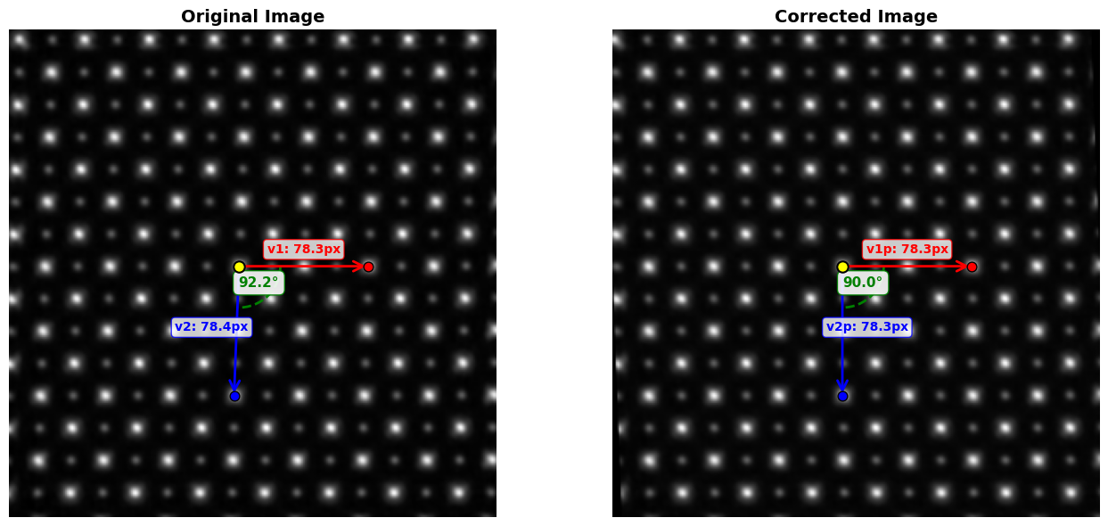
def visualize_affine_correction(img, corr, A, P0, P1, P2):
"""
Visualize the original and corrected images with annotated vectors.
Parameters
----------
img : ndarray
Original image
corr : ndarray
Corrected/warped image
A : ndarray
2x2 affine transformation matrix
P0 : ndarray
Origin point (x, y)
P1 : ndarray
First vector endpoint in original image (x, y)
P2 : ndarray
Second vector endpoint in original image (x, y)
Returns
-------
fig, axes : matplotlib figure and axes objects
"""
# Calculate transformed points
P1p = A @ (P1 - P0) + P0
P2p = A @ (P2 - P0) + P0
# Calculate vectors
v1_orig = P1 - P0
v2_orig = P2 - P0
v1p_corr = P1p - P0
v2p_corr = P2p - P0
# Calculate angles
angle_orig = np.degrees(np.arctan2(v2_orig[1], v2_orig[0]) - np.arctan2(v1_orig[1], v1_orig[0]))
if angle_orig < 0:
angle_orig += 360
angle_corr = np.degrees(np.arctan2(v2p_corr[1], v2p_corr[0]) - np.arctan2(v1p_corr[1], v1p_corr[0]))
if angle_corr < 0:
angle_corr += 360
# Calculate lengths
L1_orig = np.linalg.norm(v1_orig)
L2_orig = np.linalg.norm(v2_orig)
L1p_corr = np.linalg.norm(v1p_corr)
L2p_corr = np.linalg.norm(v2p_corr)
# Create figure
fig, axes = plt.subplots(1, 2, figsize=(14, 6))
# Arrow properties
arrow_props = dict(arrowstyle='->', lw=2, mutation_scale=20)
# ========================================
# Left panel: Original image
# ========================================
axes[0].imshow(img, cmap="gray")
axes[0].set_title("Original Image", fontsize=14, fontweight='bold')
# Plot arrows
axes[0].annotate('', xy=P1, xytext=P0, arrowprops={**arrow_props, 'color': 'red'})
axes[0].annotate('', xy=P2, xytext=P0, arrowprops={**arrow_props, 'color': 'blue'})
# Plot points
axes[0].scatter(*P0, marker='o', c='yellow', s=80, edgecolors='black', linewidths=1.5, zorder=5)
axes[0].scatter(*P1, marker='o', c='red', s=60, edgecolors='black', linewidths=1, zorder=5)
axes[0].scatter(*P2, marker='o', c='blue', s=60, edgecolors='black', linewidths=1, zorder=5)
# Add length labels at midpoint of arrows
mid1 = P0 + v1_orig * 0.5
mid2 = P0 + v2_orig * 0.5
axes[0].text(mid1[0], mid1[1] - 8, f'v1: {L1_orig:.1f}px',
fontsize=10, color='red', fontweight='bold',
bbox=dict(boxstyle='round,pad=0.3', facecolor='white', edgecolor='red', alpha=0.8),
ha='center')
axes[0].text(mid2[0] - 15, mid2[1], f'v2: {L2_orig:.1f}px',
fontsize=10, color='blue', fontweight='bold',
bbox=dict(boxstyle='round,pad=0.3', facecolor='white', edgecolor='blue', alpha=0.8),
ha='center')
# Add angle annotation
angle_pos = P0 + 25 * (v1_orig / L1_orig + v2_orig / L2_orig) / 2
axes[0].text(angle_pos[0], angle_pos[1], f'{angle_orig:.1f}°',
fontsize=11, color='green', fontweight='bold',
bbox=dict(boxstyle='round,pad=0.4', facecolor='white', edgecolor='green', alpha=0.9),
ha='center')
# Draw angle arc
from matplotlib.patches import Arc
angle1_orig = np.degrees(np.arctan2(v1_orig[1], v1_orig[0]))
angle2_orig = np.degrees(np.arctan2(v2_orig[1], v2_orig[0]))
arc_orig = Arc(P0, 50, 50, angle=0, theta1=angle1_orig, theta2=angle2_orig,
color='green', lw=2, linestyle='--')
axes[0].add_patch(arc_orig)
# ========================================
# Right panel: Corrected image
# ========================================
axes[1].imshow(corr, cmap="gray")
axes[1].set_title("Corrected Image", fontsize=14, fontweight='bold')
# Plot arrows
axes[1].annotate('', xy=P1p, xytext=P0, arrowprops={**arrow_props, 'color': 'red'})
axes[1].annotate('', xy=P2p, xytext=P0, arrowprops={**arrow_props, 'color': 'blue'})
# Plot points
axes[1].scatter(*P0, marker='o', c='yellow', s=80, edgecolors='black', linewidths=1.5, zorder=5)
axes[1].scatter(*P1p, marker='o', c='red', s=60, edgecolors='black', linewidths=1, zorder=5)
axes[1].scatter(*P2p, marker='o', c='blue', s=60, edgecolors='black', linewidths=1, zorder=5)
# Add length labels
mid1p = P0 + v1p_corr * 0.5
mid2p = P0 + v2p_corr * 0.5
axes[1].text(mid1p[0], mid1p[1] - 8, f'v1p: {L1p_corr:.1f}px',
fontsize=10, color='red', fontweight='bold',
bbox=dict(boxstyle='round,pad=0.3', facecolor='white', edgecolor='red', alpha=0.8),
ha='center')
axes[1].text(mid2p[0] + 15, mid2p[1], f'v2p: {L2p_corr:.1f}px',
fontsize=10, color='blue', fontweight='bold',
bbox=dict(boxstyle='round,pad=0.3', facecolor='white', edgecolor='blue', alpha=0.8),
ha='center')
# Add angle annotation
angle_pos_corr = P0 + 25 * (v1p_corr / L1p_corr + v2p_corr / L2p_corr) / 2
axes[1].text(angle_pos_corr[0], angle_pos_corr[1], f'{angle_corr:.1f}°',
fontsize=11, color='green', fontweight='bold',
bbox=dict(boxstyle='round,pad=0.4', facecolor='white', edgecolor='green', alpha=0.9),
ha='center')
# Draw angle arc
angle1_corr = np.degrees(np.arctan2(v1p_corr[1], v1p_corr[0]))
angle2_corr = np.degrees(np.arctan2(v2p_corr[1], v2p_corr[0]))
arc_corr = Arc(P0, 50, 50, angle=0, theta1=angle1_corr, theta2=angle2_corr,
color='green', lw=2, linestyle='--')
axes[1].add_patch(arc_corr)
# Turn off axes
for ax in axes:
ax.axis("off")
plt.tight_layout()
return fig, axes
02. Load image and pick control points (mouse and keyboard)#
Note: P0 is the origin, P1 should go roughly horizontal right (along fast scan direction), and P2 should go roughly vertical down (along slow scan direction)
# Switch matplotlib to interactive mode, need PyQt5
%matplotlib qt

# Load tif image (this can be 2D image, 3D depth stack, or virtual BF generated from 4D-STEM)
file_path ='H:/workspace/ptyrad_work/output/simu_STO/20260116_static_aff_1_0_2_2_full_N5184_dp128_flipT001_random32_p2_1obj_25slice_dz10_plr1e-4_oalr5e-4_oplr5e-4_slr5e-4_orblur0.4_ozblur1.0_ozrec_oathr0.96_oposc_sng1.0_spr0.1_dose1e8/objp_zstack_crop_08bit_iter0050.tif'
img_input = imread(file_path).astype(np.float32)
print("Input image shape (Z,Y,X):", img_input.shape)

# Create a 2D image for point selection
if img_input.ndim == 3:
    img = img_input.sum(axis=0)
elif img_input.ndim == 2:
    img = img_input

# Interactively picking 3 points, note that a window will pop up!
pts = pick_points_with_keyboard(img, n=3, step=1.0)
P0, P1, P2 = pts
for label, p in zip(['P0', 'P1', 'P2'], [P0, P1, P2]):
    print(f"{label} (x,y): {p}")
Input image shape (Z,Y,X): (25, 295, 295)
Point 0 (x,y) confirmed: (138.79, 142.66)
Point 1 (x,y) confirmed: (217.13, 142.66)
Point 2 (x,y) confirmed: (135.81, 221.00)
P0 (x,y): [138.79301711 142.65962518]
P1 (x,y): [217.13239925 142.65962518]
P2 (x,y): [135.80865969 220.99900732]
03. Calculate transformation from points#
# Switch matplotlib back to inline mode
%matplotlib inline

target_angle = 90.0      # Angle from v1 to v2 in degrees (clockwise rotation in image coords), default: 90
target_ratio = 1.0       # |v2p|/|v1p| ratio, default: 1.0
v1p_length = None        # Target length for v1p in real units (e.g., Ang or nm), default: None
pixel_size = None        # Physical size per pixel, default: None

# Get affine transformation matrix (A: 2x2 affine, M:3x3 affine with translation)
A, M = get_affine_transformation_from_points(P0, P1, P2, target_angle=target_angle, target_ratio=target_ratio, v1p_length=v1p_length, pixel_size=pixel_size)
Original vectors:
  v1 = [78.33938214  0.        ], |v1| = 78.339
  v2 = [-2.98435741 78.33938214], |v2| = 78.396
  Original ratio |v2|/|v1| = 1.001
  Original angle (v1→v2 rotation) = 92.18°

Target vectors (before optional scaling):
  v1p = [78.33938214  0.        ], |v1p| = 78.339
  v2p = [4.79690368e-15 7.83393821e+01], |v2p| = 78.339
  Target ratio |v2p|/|v1p| = 1.000
  Actual angle (v1p→v2p rotation) = 90.00°

det(B_source) = 6137.058794

Transformation matrix A (2x2):
[[1.         0.03809524]
 [0.         1.        ]]

Translation vector t:
  t = [-5.43465239e+00 -2.84217094e-14]

Final 3x3 affine transformation matrix M:
[[ 1.00000000e+00  3.80952381e-02 -5.43465239e+00]
 [ 0.00000000e+00  1.00000000e+00 -2.84217094e-14]
 [ 0.00000000e+00  0.00000000e+00  1.00000000e+00]]

==================================================
VERIFICATION:
==================================================
Original v1: [78.33938214  0.        ]
Transformed v1: [78.33938214  0.        ]
Expected v1p: [78.33938214  0.        ]
  Error: 0.000000

Original v2: [-2.98435741 78.33938214]
Transformed v2: [4.88498131e-15 7.83393821e+01]
Expected v2p: [4.79690368e-15 7.83393821e+01]
  Error: 0.000000

Transformed properties:
  |v1_transformed| = 78.339
  |v2_transformed| = 78.339
  Ratio |v2|/|v1| = 1.000000 (target: 1.0)
  Angle (v1→v2 rotation) = 90.00° (target: 90.0°)

P0 preservation:
  Original P0: [138.79301711 142.65962518]
  Transformed P0: [138.79301711 142.65962518]
  Error: 0.000000
04. Verify transformation#
# Make the corrected image
tf = AffineTransform(matrix=M) # warp is using 'inverse_map', so we're passing the inverse of M
corr = warp(img, inverse_map=tf.inverse, preserve_range=True)

fig, axes = visualize_affine_correction(img, corr, A, P0, P1, P2)
plt.show()
05. Extract affine components for PtyRAD#
# Convert A from image convention to matrix convention for PtyRAD
S = np.array([[0,1],[1,0]]) # Use this S_xy matrix to swap x,y
Ap = S @ A.T @ S # A = [[a,b], [c,d]], Ap = [[d,b],[c,a]].

ptyrad_affs = np.round(decompose_affine_matrix(Ap), 5) # Round to 4 decimals
plot_affine_transformation(*tuple((v.item() for v in ptyrad_affs)))
print("Input the following affine transformation components to 'pos_scan_affine' in PtyRAD params file")
print(f'(scale, asymmetry, rotation, shear) = [{", ".join(f"{x:.4f}" for x in ptyrad_affs)}]') # Note that rotation and shear are in degrees
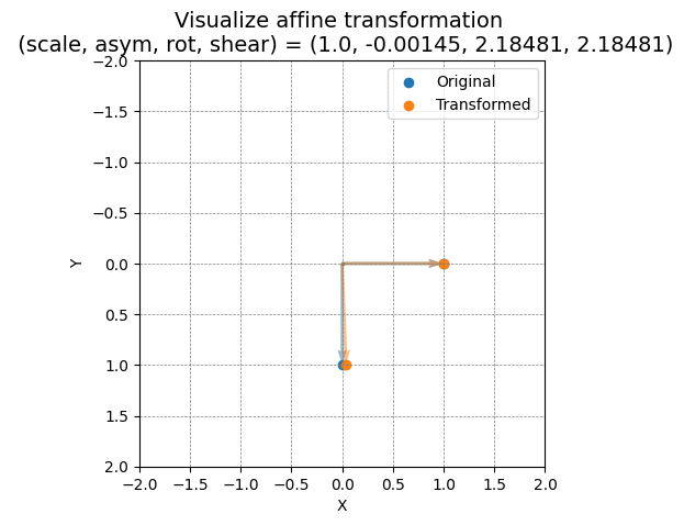
Input the following affine transformation components to 'pos_scan_affine' in PtyRAD params file
(scale, asymmetry, rotation, shear) = [1.0000, -0.0014, 2.1848, 2.1848]